≈ 10 min read · August 14, 2019
Cable sizing is very key when it comes to electrical installations. Proper sizing helps avoid overloading or underloading of cables. Overloading cables may lead to damage
Experienced engineers also know you cannot use a 1.5mm2 or 2.5mm2 cable to your consumer unit or distribution box. This is regardless of the load current calculations. So even though your load calculations may imply that 2.5mm2 cable is sufficient for power supply from a distribution board to a consumer unit, you may actually end up using a 6mm2 or even 10mm2 cable. Diversity must also be taken into consideration. This helps in preventing
Care must also be taken into when incorporating future load growth. It is not easy to predict the load growth but some engineers use values ranging from 15% to 25%.
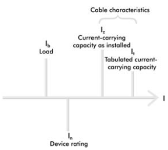
Load, Device and Cable Characteristics.
Where:
- lb is the design current; it is determined from the load to be connected to the
- ln is the rated current or current setting of the protective device.
l z is the current-carrying capacity of a cable for continuous service in its
particular installed condition.- lt is the tabulated current-carrying capacity of a cable found in Appendix F of
the On-Site Guide or Appendix 4 of BS 7671.
Ib<In<Iz<It
Where,
I b is the design current; it is determined from the load to be connected to the circuit.I n is the rated current or current setting of the protective device.I z is the current carrying capacity of a cable for continuous service in its particular installed condition.- It is the tabulated current-carrying capacity of a cable found in Appendix 4 of BS 7671.
Cable Selection
Before estimating the quantities of required cables we should understand some concepts about cable selection.
The voltage level used.
Type of loads we want to be served (static, dynamic heating loads, etc.) as the type of loading may impact the cable sizing, coating and
The distance and the route of laying.
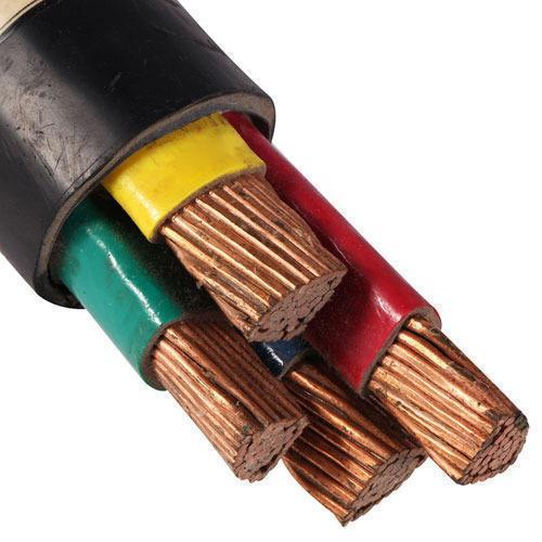
Determining the type of conductor is based on either transmission is via overhead line (OHL) or underground, in the first case it recommended to use Aluminium and in the second
The configuration to be followed either using transformers to step up and step down for
It will be useful to determine the lifetime of equipment and the importance of it to the system from economical point of view in order to select perfectly, for an example from IEEE 1205-2000 (
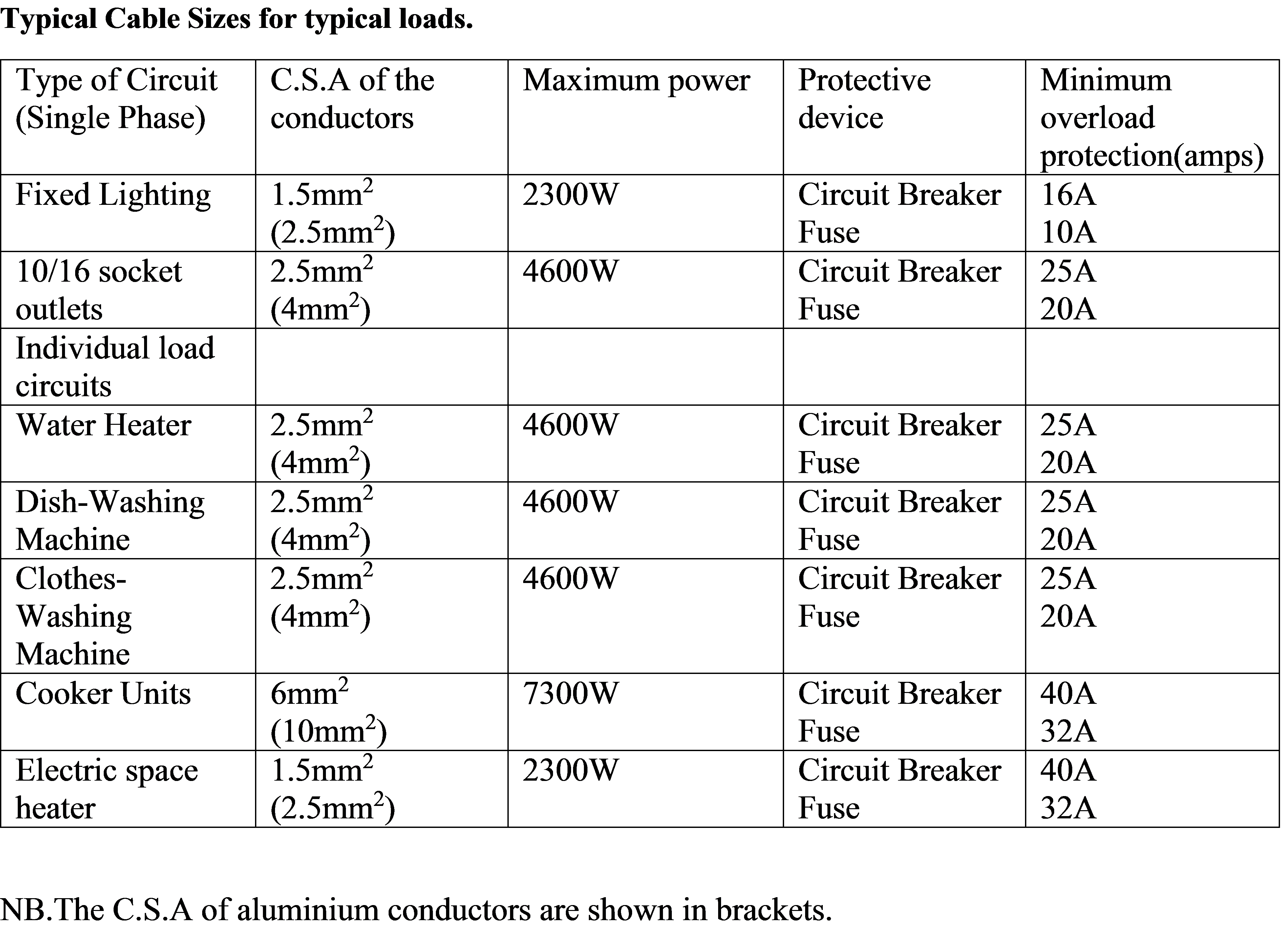
How to select the correct cross-sectional area of cables with particular single-phase loads in mind.
Referring to the tables in Appendix 4 of BS 7671, we’ll assume that the overcurrent protective device will be providing fault current and overload current which is the normal situation.
Calculating the right size
There are five steps to calculating the right size of cable for a particular load. These are as follows:
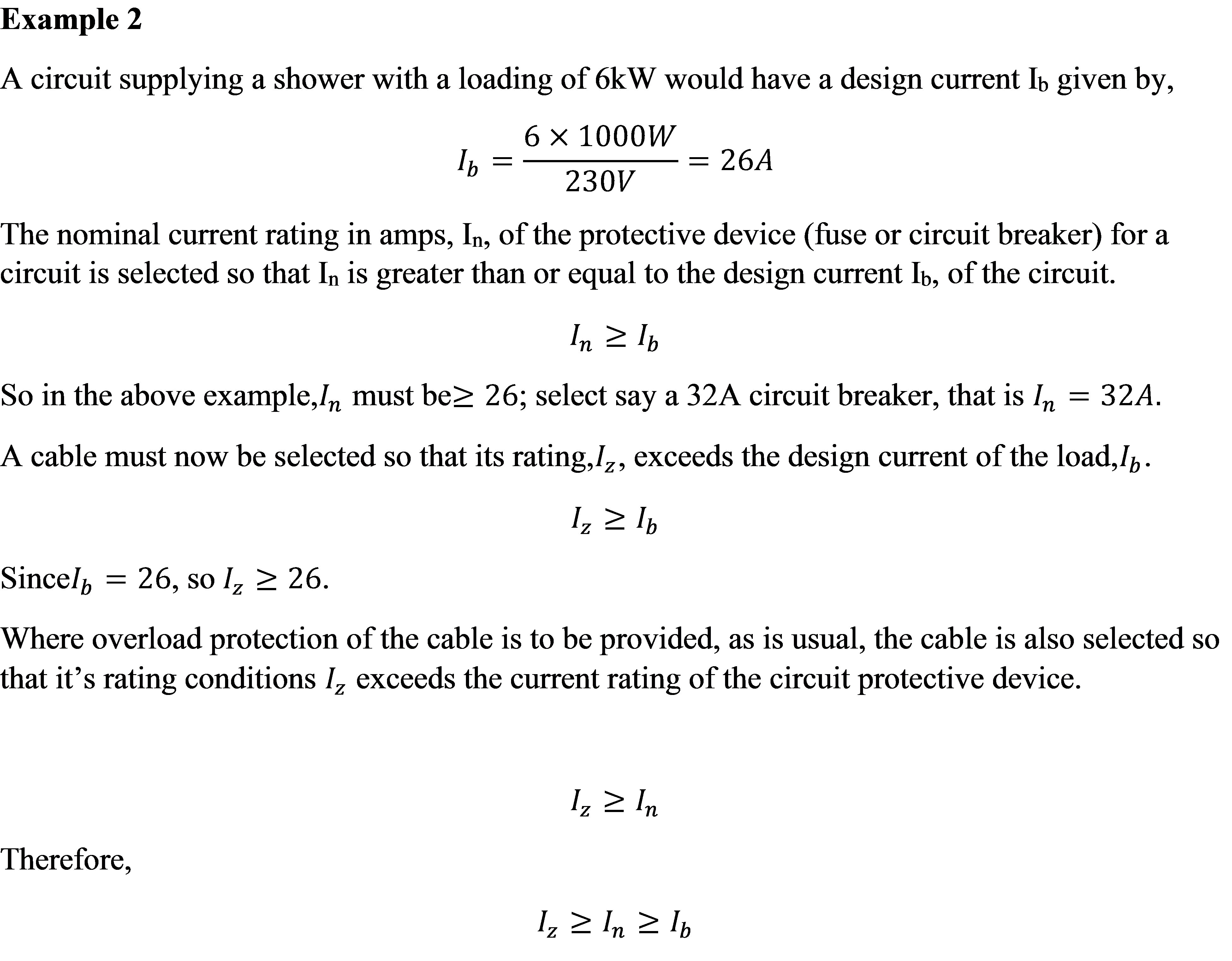
- Calculate the design current (Ib). This is the normal current drawn by the load. It is usually determined as follows:

2
Ambient temperature, Ca
This factor is obtained from Table 4C1 (or Table 4C2 if are
Grouping, Cg
This factor is found by reference to Table 4B1 in Appendix 4. Table 4B2 is used where mineral insulated cables are installed on
Thermal insulation, Ci
Where a cable is in contact with thermal insulation on one side only, the current-carrying capacity of the Cable is calculated using Reference Method 4, which is described in Appendix 4 (Table 4A) of BS7671.
Where a cable is totally surrounded by thermal insulation for a distance greater than 0.5 meters, the current-carrying capacity should be taken, in the absence of further information, as 0.5 times the current-carrying capacity for that cable when using Installation Method 1 (open and clipped direct).
Where a cable is totally surrounded by thermal insulation for a distance of 0.5 meters or less, Table 52A in BS7671 gives derating factors which must be applied.
Rewireable fuse (BS 3036) factor, Cr
Where a rewireable fuse to BS 3036 is used, a further correction factor of 0.725 is applied, due to the poor fusing factor of rewireable fuses.
How to apply correction factors
These correction factors are applied as divisors to the nominal current rating of the overcurrent protective device (In)), to obtain the tabulated current,

The more correction factors we apply, the larger the value of it will be and hence the larger the size of cable we will require. Consequently, it is advantageous to avoid having to apply correction factors where possible by, such measure as, avoiding grouping of cables and avoiding contact with thermal insulation.
However, the formula given above is based on the assumption that the conditions requiring the application of correction factors apply simultaneously to the same part of the cable along its route. Where particular correction factors are appropriate to different parts of the cable along its route, each part can be treated separately. Alternatively, only the correction factor
- The current-carrying capacity of the cable (which is termed Iz)) is then selected from the appropriate table in Appendix 4 of BS 7671. Iz should be at least equal to or slightly greater than the tabulated current, It.
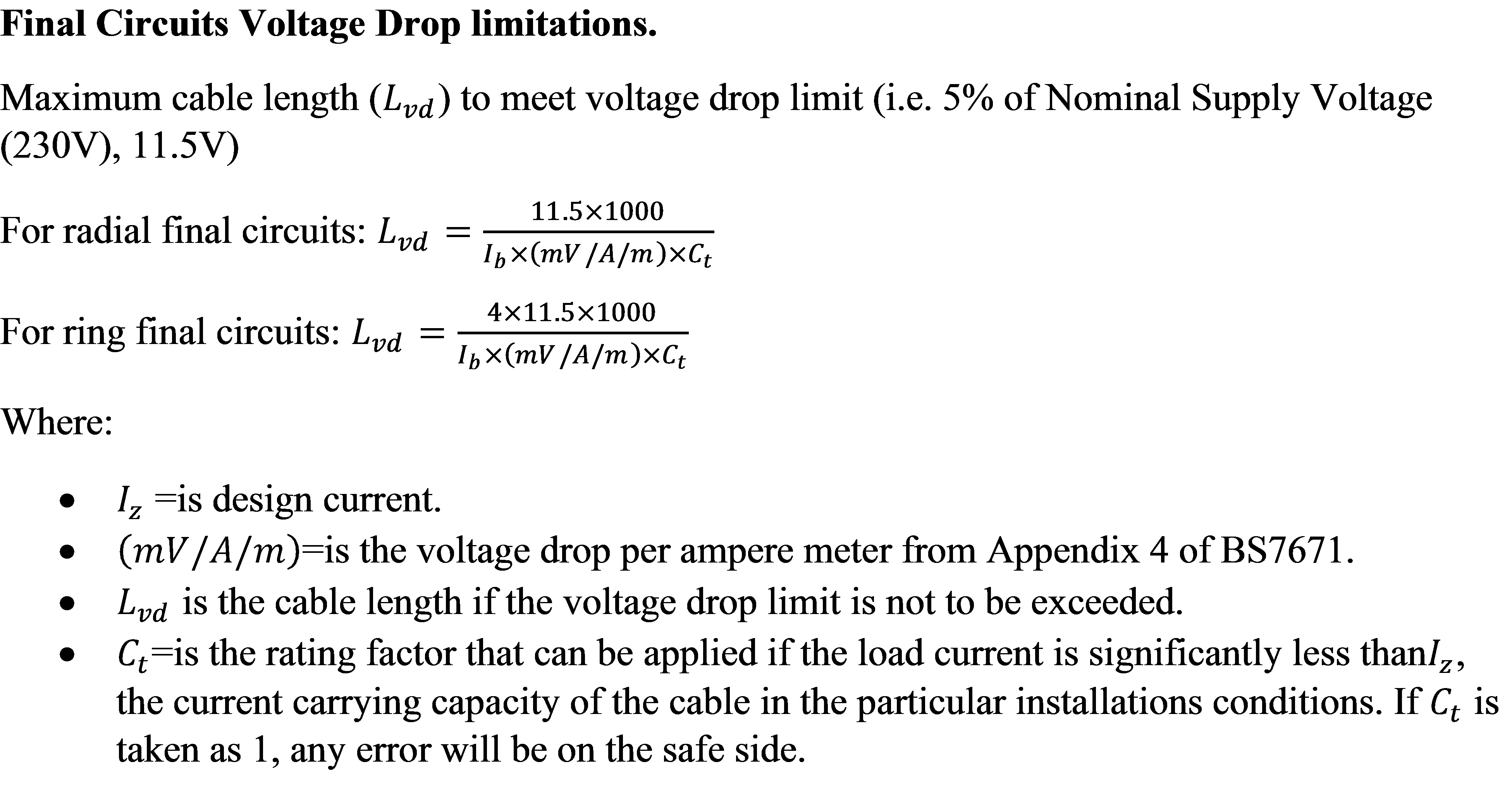
- Calculate the voltage drop to ensure that it is not excessive. Regulation 525-01-02 states that the voltage drop from the origin of the supply to the furthest point in the installation must not exceed four per cent of the supply voltage when the conductors are carrying full load current. The tables in Appendix 4 of BS 7671 have a voltage drop section in which the millivolt per amp per metre (mv/a/m) of a particular cable may be obtained. The voltage drop is calculated from:

As four
With the initial cable conductor size determined and the load known,
Voltage drop is calculated or checked prior to
Example 1:
A 6kW load is to be supplied at 230V by a PVC sheathed and insulated twin and
Answer,
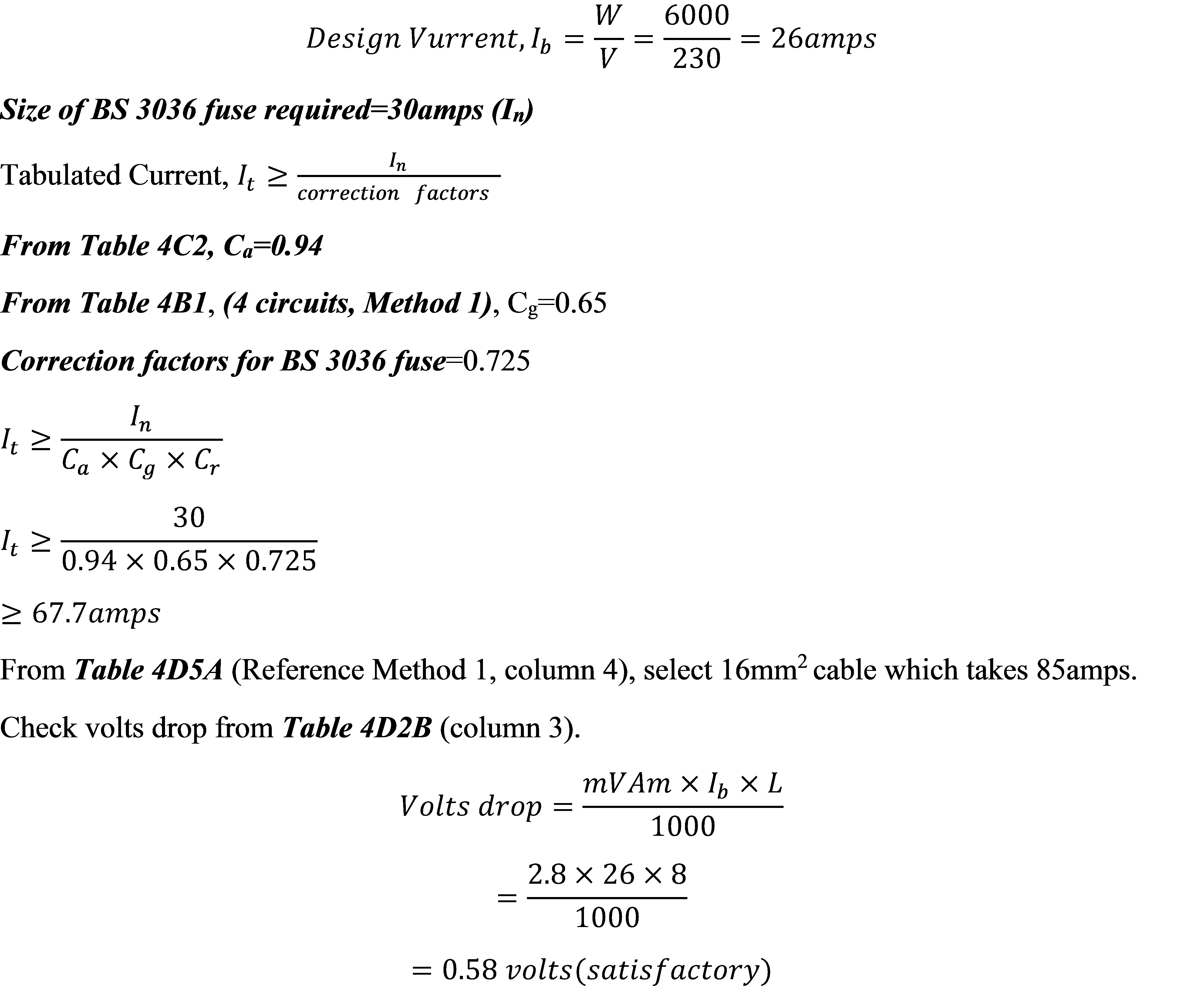
Note: If the load current exceeds the current that can be accommodated by the largest cable in the BS 7671, you can opt to use double cable (combined cables) for each particular phase.
The National Electrical Code recommends, for reasonable efficiency of operation, that the maximum total voltage drop over both feeders and branch circuits to the farthest outlet of power, heating and lighting loads not exceed 5% of the nominal system voltage. Also, conductors for feeders and for conductors for branch circuits should be sized to prevent a voltage drop exceeding 3% at the farthest outlet.
If voltage spread exceeds acceptable limits or is not suitable for a critical load, any of four basic ways may be used to reduce the spread:
- Lengths of conductors carrying the lowest voltage should be shortened and lengths of conductors carrying higher voltages should be lengthened.
- System impedance should be reduced.
- Voltage regulators should be installed on buses and feeders to compensate for voltage drop.
- Capacitors should be installed to improve the power
factor, because smaller currents flow as power factor is increased.
Other Resources:
This has been very educative and helpful. Thanks a bunch for sharing.
You are welcome.
Glad to read your blog, Benard! I am very thankful that you shared such an amazing article about Cable Sizing Guide and your website is really amazing, It is very smooth and easy to use. Keep such blogs. Waiting for more blogs.
Thank you Evan, I am glad you have found this useful.
Good work
Good work
Good work! However, how do calculate voltage drop when the let of the cable is not given?
Thanks for sharing
I wish to know size of copper cable for a
grass lawn cutter machine having 1 hp single phase motor, 220 Volt power supply.
Thank you so much for sharing.
Thanks for sharing,,,been helpful
Helpfull. Thanks.
so helpfull engeneer …be blessed
Thanks Eng. This both useful and practical. Great!
Thanks for sharing, keep it up
Thank you Eng. Makaa. The article was very helpful.
Here is a tool to assist https://cable-sizer.com/