Where would your business be without a constant supply of electrical power? A steady power supply is often taken for granted. The reality is that power failures happen more frequently than we think.
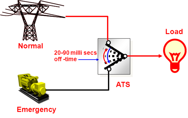
In the event of a power interruption, an ATS switches power from commercial sources to the emergency backup anywhere from 30 to 60 milliseconds. The average human eyeblink happens in 400 milliseconds.
Closed Transition Transfer Switch is a type of Automatic Transfer Switch. Basically, an automatic transfer switch is an electrical switch that automatically switches a load between two sources, say, between the grid and the back generator. An Automatic Transfer Switch (ATS) is often installed where a backup generator is located, so that the generator may provide temporary electrical power if the utility source fails.
Automatic Transfer Switches are critical components of any emergency or standby power system.
Types of Automatic Transfer Switches (ATS)
A.Open-transition switches.
An open-transition ATS utilizes a break-before-make system, meaning your transfer switch will break contact with the previous power source (grid versus generator) before establishing new contact. This system does create a brief total loss of power, but a stable connection is reached within seconds. Many smaller businesses, or businesses where a two second or so delay will not hamper processes utilize open-transition switches. These switches are the most widely used and tend to be highly reliable due to the sheer simplicity of the device and its processes.

B.Standard or “fast” closed-transition.
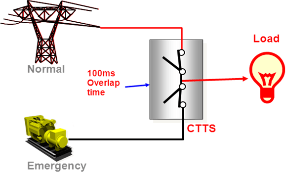
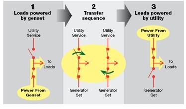
Is also called a make-before-break transfer switch. These operate on essentially the same principles of an open-transition system, but the switch will maintain contact with both power sources (grid and generator) until a stable connection is established. Connection is held usually for roughly a tenth of a second, so there’s no real danger of back feeding or harmful overlap. Since these systems avoid the power interruption of an open-transfer switch, they are often used by businesses that can be harmed by even the briefest losses of power. Most often these are large-scale commercial businesses, hospitals, data centers, etc.
Control logic continuously monitors source conditions and automatically determines whether the load transfer should be open (conventional non-overlap mode) or closed transition. Available 150 through 4000 Amperes.

C.Delayed-transition systems.
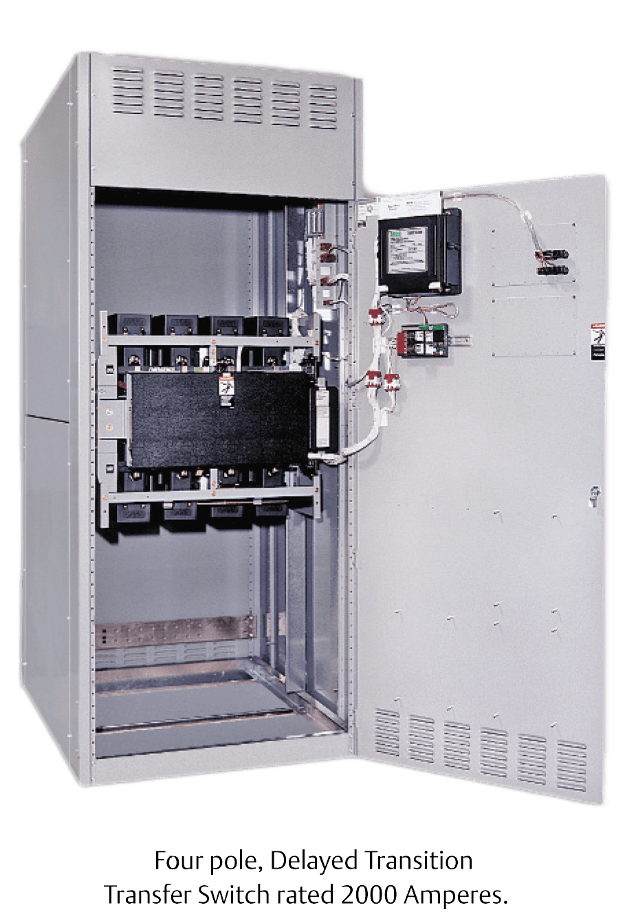
With these ATS systems, a break-before-make is still established, much like an open system, but there is an engineered and purposeful delay before the switch from grid to generator power is made (and vice-versa). This delay acts as a failsafe against power surges that can be common to heavy industrial equipment when powered on and off within seconds.

Closed Transition Transfer Switches
A Closed Transition Transfer Switch (CTTS) simply takes advantage of the latest technological advances to avoid the momentary interruption during some of the transfers. The switch logic determines if both source voltages and frequencies, and the phase relationship between the sources, are within acceptable limits. If all conditions are correct, the switch contacts are allowed to make an overlap (make before-break) transfer. This avoids the momentary interruption or the load that occurs with traditional break-before- make transfer switches. If the source feeding the load has railed, a CTTS automatically reverts to open transition transfer operation.

Merits of Closed Transition Transfer Switches
- CTTS can eliminate momentary power interruptions when transferring between two synchronized and acceptable sources. Since there is a smooth transition between sources, the stress on the downstream loads is reduced. The engine generator recovery from the step loading associated with a traditional ATS may be reduced.
- Power can be shifted without interruption from a utility to an on-site source when a storm is approaching or a brownout or voltage reduction is anticipated.
- Inrush currents associated with motor starting and transformer switching are eliminated during closed transition transfers.
- The restart time associated with metal halide and other HID lighting is eliminated during closed transition transfers.
Where they are needed
- If a load is sensitive to the momentary off time when transferring between two acceptable sources, then a CTTS should be considered.
- Where there is a reluctance to meet code required periodic testing, for transferring transformer loads, to reduce stress on UPS systems and their batteries, for elevator switching, for utility peak-load reduction and load demand reduction applications and other similar applications.
Note:
- The utility company (say, KPLC in Kenya) should always be consulted before any alternate source is connected to their lines for any length of time for approval. Modern CTTS contain an integrated, computerized, sensing and protective logic panel which will only permit paralleling an acceptable engine generator source with an acceptable utility source. The maximum parallel time will not exceed 100 milliseconds. Separate external protective relays may not be needed since these functions are built into the CTTS.
- A CTTS is not a substitute for Uninterruptible Power Supply (UPS). A UPS is meant to carry a load for short periods of time in the event of a power source failure. Some power systems feed critical loads via the UPS. An engine generator and transfer switch are often used to provide and alternate source of power for the UPS so that the load can remain reliable energized for extended periods of time. Each time the UPS loses its source of power, the batteries are stressed, reducing their life to some degree. A CTTS minimizes the off times. The cost of a CTTS over a traditional ATS could be offset by the potential savings in replacement UPS batteries.
- Additional protective relaying and active synchronization is not needed on a CTTS as long as the CTTS operates within 100 milliseconds and overcurrent protection as required by Article 240 of the National Electrical Code is provided.
- The type of protective relays used in cogeneration, peak-shaving or multiple engine paralleling systems typically require more than 100 milliseconds to sense and react. They would serve no purpose on a high-speed CTTS. They may be needed in closed transition switches that remain paralleled for longer periods of time. Similarly, active synchronization is not needed to hold the generator steady while the operator moves. Also, an engine generator’s governor cannot accept multiple external signals. This conflict would occur if there are multiple closed transition transfer switches each with their own active synchronizer, and a single engine generator set.
- Safeguards are built into MODERN CTTS to prevent inadvertent paralleling of both sources. In the unlikelihood that both sets of contacts should remain closed for more than 100 milliseconds, the lost operator to close will automatically reopen. An alarm is indicated and the system locks itself out requiring a manual reset. If both operators should ever fail simultaneously (extremely unlikely) while their contacts are both closed, a dry contact in the logic will close.
There are risks associated with closed transition transfer switches as two live sources are connected together.
Problems with closed transition transfer originate from a difference in voltage between the two sources at the instant when the two sources are connected. The difference in voltage can be caused by several factors:
- A difference in root mean square (RMS) voltage between the sources
- A phase angle difference between the two sources
- A transient condition on one of the sources caused by a load switching on or off, or instability of one of the sources.
The instantaneous voltage difference between the sources results in a current surge from the source with the higher voltage to the source with the lower voltage at the instant of the sources’ interconnection. This current is limited only by the impedance of the sources and the current-carrying capacity of the cable or bus connecting them. It is this current surge that can trip breakers or, in more extreme cases, damage equipment.
Recommendations for minimizing risks of out-of-phase closure include:
- Recognize that all sync check systems allow for sources to be a few degrees out-of-phase at closure, resulting in some level of surge current between the sources. Breakers, transfer switches, and cable must be sized accordingly.
- Consider active synchronizing with voltage matching to minimize the phase and voltage differences between sources.
- Minimize transient conditions at the moment of transfer by inhibiting multiple transfer switches from transferring at the same time and preventing other loads from cycling during the transition.
- Use a transfer switch “fail to disconnect” or maximum parallel timer relay to shunt-trip an upstream breaker to prevent extended paralleling in the event that a transfer switch fails.
Phase difference at closure: How much is too much?
Very rarely will two sources be exactly in sync at the instant that a switch or breaker closes the two sources together, so it is reasonable to ask how far out-of-phase two sources can be and still have a reliable closed transition. IEEE 1547 allows generator sets or systems of paralleled generator sets between 1.5 and 10 MVA to be up to 10 deg out of phase with the utility when closing to the grid, with higher phase difference limits for smaller systems.
Alternators typically can handle connecting to a source that is 10 deg out of phase with it. For other equipment the answer depends on how much surge current the system can handle without tripping breakers or damaging equipment. For high reliability, one must consider the magnitude of current that can flow between the sources at the instant of transfer.
The surge current will be proportional to the voltage difference between the phases divided by the total impedance in the system.
Sources:
- IEEE Conference Paper – Closed Transition Switching of Essential Loads.
- ASCO 436 Automatic Closed Transition Transfer Switches.
- EC&M Reprint – Transfer Switching Without Load Interruption.
- ASCO Facts – Transferring Loads with Zero Power Interruption.
- https://en.wikipedia.org/wiki/Transfer_switch
- Managing risks, benefits with closed transition transfer switches by Rich Scroggins, Cummins Power Generation, Shoreview, Minn.
