
Fire Detection and alarm systems are designed to provide warning to the outbreak of fire thus allowing evacuation and appropriate firefighting action to be taken before the situation gets out of control.
When designing a fire detection and alarm system, in addition to deciding the type of system, detectors, call points and sounders to be used etc. Other aspects to be considered include:
- Measures to limit false and unwanted alarms.
- Method of installation.
- Materials required during installation.
- User training,
- Routine maintenance procedures, and service agreement.
- As a general rule, conventional systems are appropriate only in buildings of limited size and complexity, where a simple indication of the zone in which there is a fire will be sufficient. In other buildings, an indication of the exact location of the detector’s that has responded to a fire, provided by an addressable system, will be of value.
Categorization of fire alarm and detection systems.
Property Protection Fire Systems
- P: AFD designed to primarily protect property categories:
- P1: AFD installed throughout all areas.
- P2: AFD installed only in defined areas.
Life Protection Fire Systems
- L :AFD designed to primarily protect human life categories:
- L1 :M plus AFD installed throughout all areas
- L2 :AFD installed in defined areas of higher risk of ignition, in addition to L3
- L3: M plus AFD installed in escape routes and rooms opening into these routes
- L4 M plus AFD installed in escape routes comprising circulation areas and space such as corridors and stairways
- L5: A non-prescriptive system in which protected area(s) and/or the location of detectors is designed to satisfy a specific fire risk objective (other than that of L1 to L4).
*AFD – Automatic Fire Detection
M- System designed to be operated manually (no AFD)
Design Stage 1
Talk to the interested parties to decide on the level of protection or category and agree Variations
The importance of pre-design planning cannot be overstated. Many parties are likely to have an interest in what the fire detection is expected to do. Ultimately it is up to the Owner/Occupier, who is responsible by law, to make the final decision on the level of protection provided for a particular building. In most circumstances the Owner/Occupier will appoint a competent Designer to carry out this work and take liability for the design as a whole.
The nominated Designer is expected to consult the following organizations:
- The User or Facilities Manager
- The Building Control Officer
- The Health and Safety Executive
- The Insurer
- The Local Fire and Rescue Service
- A specialist fire alarm system supplier
Issues to be covered by the designer should include:
- The Fire Risk Assessment demands
- The requirements necessary to comply with the Regulatory Reform
- prime purpose of the system (Property or life protection or both)
- The level of protection suggested by the interested parties. (Category P1 or P2, M or L1 L2 L3 L4 or L5
- The list of Variations identified by the interested parties
Determine the System Category or Level of Protection
Systems designed for Protection of Property only, fall into two classifications P1 or P2.
- The objective of a Category P1 is to provide the earliest possible warning of a fire to minimize the time between ignition and the arrival of the fire fighters.
- P1 is designed to protect the whole building whilst P2 is installed in defined parts of the building only, which may have an extraordinary high risk or hazard.
- Life protection on the other hand will often depend on the number of people accessing a particular building and depending on the variations, the systems can range from simple Type M to L1 categories, these being detailed in the diagrams on this page.
- A Category M system requires manual call points on all exits as well as corridors where persons are not expected to walk more than 45m.
- Category L5, designed for buildings that have a particular risk identified which warrants some special attention. For example if there is an area of high risk which is considered worthy of having some automatic detection but a manual system is also needed, then this will be termed as L5/M.
- Category L4 provides detection within the escape routes only, whereas L3 not only covers these areas but all rooms leading onto the escape route. The reasoning behind this is to alert people of the danger prior to the corridor becoming “Smoke logged” so people can escape safely.
- L2 is a further enhancement of protection with all the areas covered by an L3 category as well as all high risk areas such as boiler rooms etc.
- L1 provides protection throughout the building, and also where Property Protection is the prime reason for the system (this allows for a choice between the P1 or P2 categories). M
Design Stage 2: Detection and Alarm Zones
Generally a building is broken down into smaller compartments to enable the fire fighters to locate the fire as quickly as possible.
Even if the system is addressable it is still considered beneficial to have a separate ‘at a glance’ indication of the location of the fire.
These compartments of a building are called detection zones, which need to comply with the following criteria.
Detection Zones
- A detection zone should cover no more than 1 storey, unless total floor area is less than 300m2. Voids in the same fire compartment should be included in the same floor zone. The maximum floor area of a zone should not be greater than 2,000m2, except for some large open plan areas incorporating manual call points only, which can be extended to 10,000m2
- The maximum search distance for the fire fighters to see the seat of the fire within a zone should not exceed 60m assuming the route taken is the worst possible option.
- Vertical structures such as stairwells, lift wells etc. should be considered as separate zones.
- A manual call point within a staircase should be connected to the zone associated with that floor and ideally be mounted on the accommodation side of the corridor exit. Automatic sensors on the stairwell remain as part of the stairwell detection zone.
Alarm Zones
An alarm zone is clearly defined within the standard but generally is an area of the building coinciding with the fire compartment boundaries. There must be a clear break between these alarm zones to ensure alert and evacuation messages are not overheard from adjacent areas.
The only other criteria is that an alarm zone may consist of a number of detection zones but not vice versa.
Alarm zones are only required when phased or staged evacuation is required. It is therefore important that care should be taken to ensure only one message is heard at any one time particularly where two alarm zones are attached.
Design Stage 3: Siting of Manual Call Points
All manual call points, whatever the system, should comply with BS EN54-11 single action Type A version only and should be located as follows:
- all storey exits and all exits to open air irrespective of whether they are designated fire exits
- Nobody should travel more than 45 meters to reach one, except if the exit routes are undefined in which case the direct line distance should not exceed 30 meters.
- The above distances to be reduced to 25 and 16 meters respectively, if there are persons with limited mobility or there is a likelihood of rapid fire development.
- In all areas with potential high fire risk such as kitchens etc.
- Where phased evacuation is planned, call points will need to be sited on all exits from a particular zone.
- 4 meters + or – 200mm above the floor.
- Call points fitted with protective hinged covers for whatever reason should be listed as a Variation.
Design Stage 4: Selection and Siting of Sensors
The objective is to select the correct sensor for the appropriate application, to provide the earliest warning of fire without the risk of a false alarm.
It is therefore worth trying to visualize the type of fire that is likely to occur in a particular room or area and also to familiarize oneself with the application and the risks that could give rise to a false alarm.
Design Stage 5: Choice and Siting of Alarm Sounders and Visual Alarms
Sounders and strobes are generally provided for systems designed to protect life. However, on the rare occasion when only the property is being protected it is still essential to mount a sounder adjacent to the fire control panel as well as immediately outside the main entrance for the fire fighters.
- Before deciding on the number and location of sounders/visual alarms, it is important to establish the ‘Fire Plan’ or cause and effect.
- If the building is not going to have a ‘one out – all out’ arrangement, the evacuation procedures must be established. Once this is known, you can then establish the alarm zone areas where different alarm messages may be given, for example an alert or an evacuation tone.
- Audible alarm levels within buildings are generally accepted as 65dB (A) throughout. However, the new Standard does accept that in certain locations this can be as low as 60dB (A). This allows some degree of flexibility, although in general the majority of a site must achieve 65dB (A) or greater to be compliant.
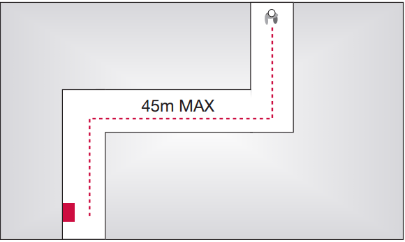
- For areas with high ambient background noise levels, the Standard recommends a sound level of 5dB (A) above the norm although the maximum sound levels should not exceed 120dB (A) for health & safety reasons. It is essential that at least one sounder is placed within each fire compartment and the sounder choice should be common throughout the building. Bells and electronic sounders should not be mixed within the same building.
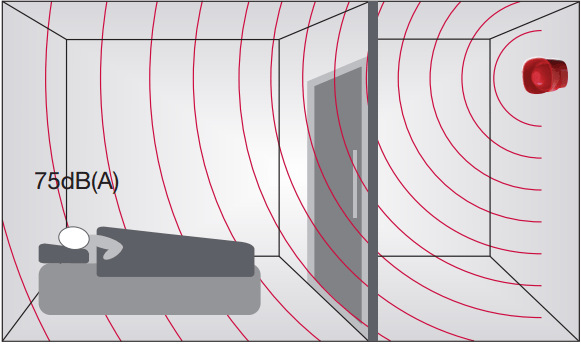
- It is maintained that to rouse sleeping persons you need to achieve a minimum of 75dB (A) at the bedhead.
- Sound attenuation is affected by numerous physical structures within a room, including the people, door, furniture and materials used for floor, walls etc.
General internal doors will attenuate at least 20dB (A), whilst heavier fire doors may well attenuate by up to 30dB (A). To ensure 75dB (A) is achieved within a bedroom it is accepted that the sounder is mounted within the room rather than the corridor outside. Use of sensor sounders ensures an even spread of sound throughout the building without the need for separate louder sounders. Visual alarms are generally considered as supplementary rather than the only means of providing an alarm, and are used in areas where the dB (A) level exceeds 90dB (A) or where persons within the area have impaired hearing. The exception could be where sound of any description is undesirable, for example operating theatres, TV studios and places of entertainment where a discreet staff alarm system is the best option to avoid panic.
Visual alarms are also included as a requirement of the Disability Discrimination Act and Approved Document M of the Building Regulations and should be included in all sleeping accommodation where people with a hearing disability may be present.
Typical sound pressure level at various distances.
Voice Alarm Systems and Voice Sounders.
Instead of using fire alarm sounders, audible alarms may comprise voice messages generated by a voice alarm system. A voice alarm system is a specially designed sound distribution system (i.e. public address system), which, in the event of
The minimum sound level of a sounder device should be 65dB (A) or 5dB (A) above
Sounders and strobes are generally provided for systems designed to protect life. However on the rare occasion when only the property is being protected it is still essential to
Before deciding on the number and location of sounder/visual, alarms it is important to
establish what the ‘Fire Plan’ or cause and effect will be.
If the building is not going to have a one ‘out all’ out arrangement the evacuation procedures must be established. Once this is known you can then establish the alarm zone areas where different alarm messages may be given for example an alert or an evacuation tone.
Research over the last twenty years has proven that a voice enhanced sounder is preferred to a bell or electronic sounder as people pay more attention to a spoken message.
Sounder device cabling should be arranged so that in the event of a fault at least one sounder located within the vicinity of the control and indicating panel will remain in operation.
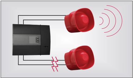
The maximum zone floor area should not exceed 2000m2. A person searching a zone for a fire should not have to travel more than 60m from the zone entrance to identify the source of the fire.
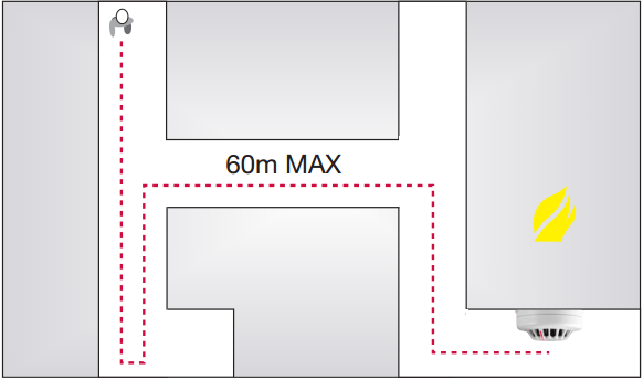
A person should not have to travel more than 45m along an escape route to reach a manual
The centre of the element of the manual
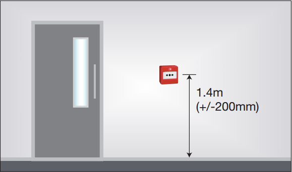
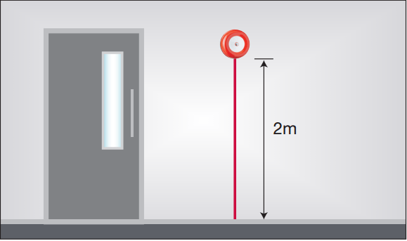
Visual alarms such as beacons should always be mounted at a minimum height of 2.1m from floor level, in a position that is likely to attract attention.
Unless MICC or armoured cable to BS7846 standard is used, consideration should be given to the protection against physical damage from floor level to the height of 2m. Except in relatively benign areas, such as shops, offices and similar, where cabling can be clipped to robust walls.
For areas where people are sleeping, sounder devices should produce a minimum 75dB (A) at the bed-head with all doors shut. In buildings likely to provide sleeping accommodation for the hearing impaired, consideration should be given to the incorporation of both audio and visual devices.
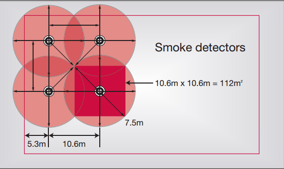
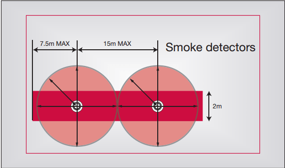
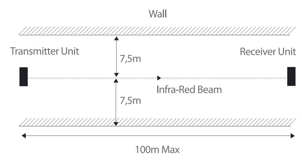
When mounted on a flat ceiling, smoke detection devices have an individual coverage of 7.5m radius.
When mounted on a flat ceiling, Heat detection devices have an individual coverage of 5.3m radius.
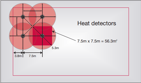
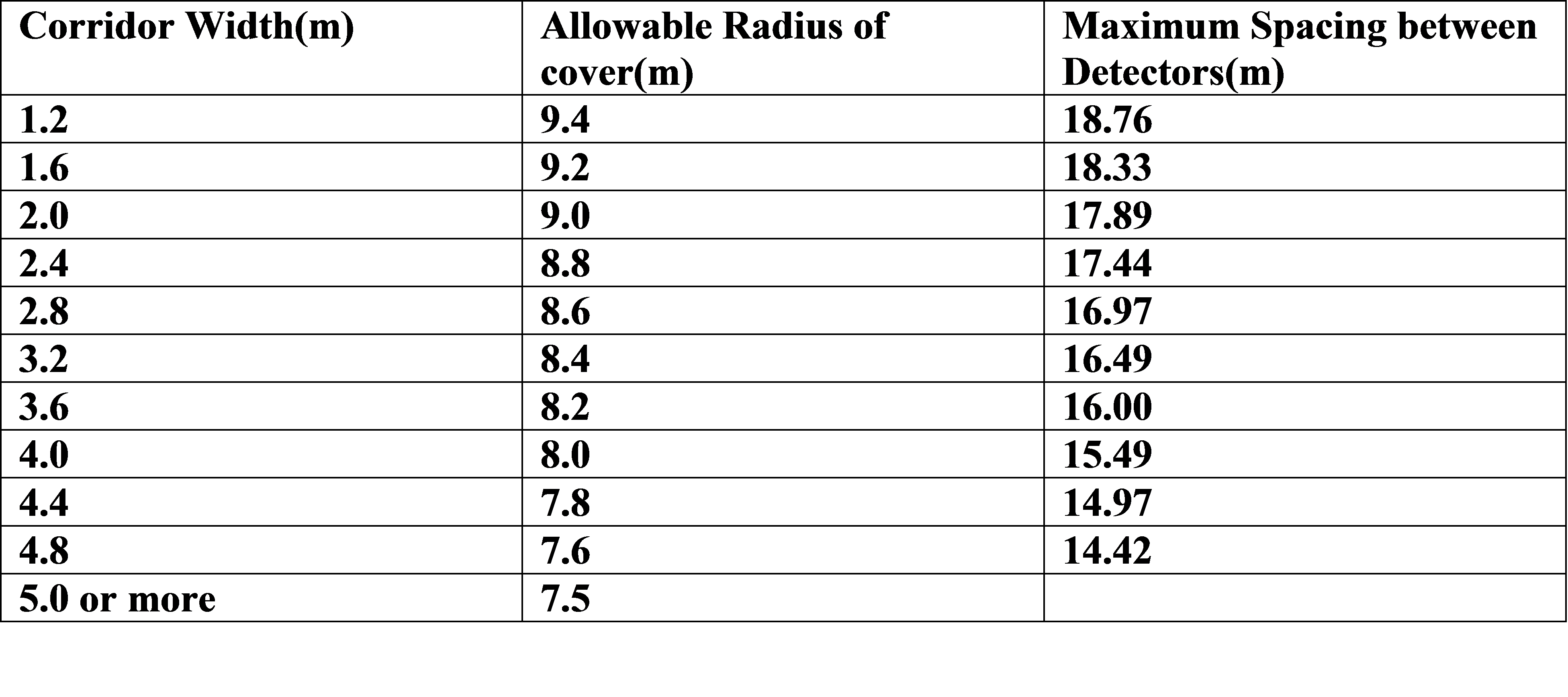
In corridors less than 2m wide the horizontal spacing of detectors can be increased, the area of coverage need not overlap as in the case of a room. Any corridor over 2m wide is deemed as a room and must adhere as specified.
Note: Heat detectors are not recommended for use in corridors that may be used as escape routes.
For ease of design and assessment of coverage dimensions used for detectors are usually taken as:
- Smoke: 5m to wall / 10m between detectors Coverage 100m2
- Heat: 3.5m to wall / 7m between detectors Coverage 50m2
Decibel loss occurs through doors: Approximately -20dB (A) through a normal door, and approximately -30dB (A) through a fire door. Unless a sounder is installed in a bedroom, it is unlikely that 75dB (A) will be achieved.
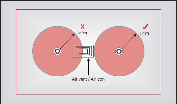
Do not site detectors less than 1m from air inlets or air circulating systems. The minimum distance between the two should be at least 1 metre and further if possible. This is due to the fact that smoke may have difficulty penetrating the sensor when the air conditioning is switched on. Also there is a greater risk of the sensor becoming contaminated and giving rise to false alarms.
For ceilings that feature an apex: As long as the height of the apex from the rest of the ceiling is less than 150mm for heat detectors or less than 600mm for smoke detectors, then these can be treated the same as flat ceilings. For higher apexes, a device should be installed at the highest point. The distance to adjacent devices can be increased by 1% per degree of angle of the roof up to a maximum of 25%.
Design Stage 6: Control equipment and power supplies
The Control panel itself should comply with EN54-2 and any power supply used should comply with EN54-4. A good fire control panels should incorporate their own battery and charger. It is however recommended that a battery load calculation is carried out to verify the standby period provided by the capacity of the battery supplied.
Irrespective of the size or type of system the control panel should be sited with the following points in mind;
- In an area of relatively low fire risk
- On the ground floor entrance which the
fire fighters will use - In buildings of multiple
occupancy , the panel should be sited within a communal area or if this does not exist, a location which is accessible at all times - Where ambient light levels, ensure visibility at all times
- Fire zonal indication should be clearly displayed by LEDs or an illuminated mimic diagram – it is not acceptable to simply accept the information from an LCD or VDU display.
- If there are several entrances to the building, consideration should be given to the provision of repeat indicators.
Power Supplies
Virtually all systems will be powered from the public mains supply, with a secondary standby supply being provided by rechargeable batteries (sometimes in conjunction with a standby generator). If the standby batteries are supplemented by an automatically started generator, it is permissible to reduce the standby battery capacity of Category M and L systems.
Both the primary mains supply and the secondary standby supply must be able to provide the maximum load independently of each other. The alarm load of the fire alarm system is the maximum load which the power supply must provide under fire conditions. This includes power drawn during simultaneous operation of the control and indicating equipment, all sounders, all detectors, all manual call points and transmission of signals to an alarm receiving centre.
Mains Supply
Any switch (other than the main isolator for the building) that disconnects the mains supply to the fire alarm system should be clearly labelled ‘FIRE ALARM: DO NOT SWITCH OFF’.
Any protective device (such as a fuse) that serves only the fire alarm circuit should be labelled ‘FIRE ALARM’.
The circuits supplying the fire alarm system should not be protected by residual current
To facilitate local isolation during maintenance, a double pole switch should be provided in the vicinity of the control and indicating equipment (and any other mains supply equipment forming part of the fire alarm system) so that maintenance technicians can isolate the mains supply to the fire alarm system locally to the equipment that the mains supply serves. The switch should be lockable to present unauthorized operation.
The presence of the normal or the standby supply should be indicated by a green indicator at the main control and indicating equipment, to show that power is being supplied to the system (whether from the mains supply or the standby supply).
Standby Supply.
The standby supply should be provided by secondary batteries with an automatic charger. The batteries should have an expected life of at least four years; the code specifically disallows the use of car–starting type batteries.
In order that the full life of the batteries is achieved, it is important to ensure that the characteristics of the charger match those of the batteries being used. The charger should be capable of charging fully discharged batteries in 24 hours.
In the event of a mains supply failure, the capacity of the standby supply must be likely to provide protection until the normal mains supply has been restored.
Life Protection (Category M and L Systems)
The capacity of the standby batteries should be sufficient to operate the system for 24 hours normal operation, and also have sufficient capacity remaining at the end of this period to provide an evacuation signal throughout the building for 30 minutes.
If the building is provided with an automatically started standby generator that serves the fire alarm system (usually in conjunction with other essential supplies in the building), the capacity of the standby batteries should be sufficient to maintain the system in operation for at least six hours, after which sufficient capacity should remain to provide an ‘evacuate’ signal in all alarm zones for at least 30 minutes.
Property Protection (Category P Systems)
The capacity of the standby batteries required for property protection systems is identical to that required for Category M and Category L systems (i.e. sufficient to operate the system for 24 hours and provide an evacuation signal for 30 minutes thereafter) PROVIDED:
- The building is continuously manned, so that staff in the building would be aware of a power supply fault indication on the system within no more than six hours of its occurrence; or
- The building is inspected outside normal working hours such that staff would be aware of a power supply fault indication within no more than six hours of its occurrence; or
- Power supply fault signals are transmitted automatically to an alarm receiving centre, instructed to notify a
key holder immediately on receipt of a fault indication from the premises.
In all other circumstances, the battery capacity should be sufficient to maintain the system in operation for at least 24 hours longer than the maximum period for which the premises are likely to be unoccupied, or for 72 hours in total, whichever is less, after which sufficient capacity should remain to operate all fire alarm devices for at least 30 minutes.
Calculation of Standby
Battery Capacity.
For systems designed in accordance with BS 5839-1, compliance with the code requires that the battery capacity of valve regulated
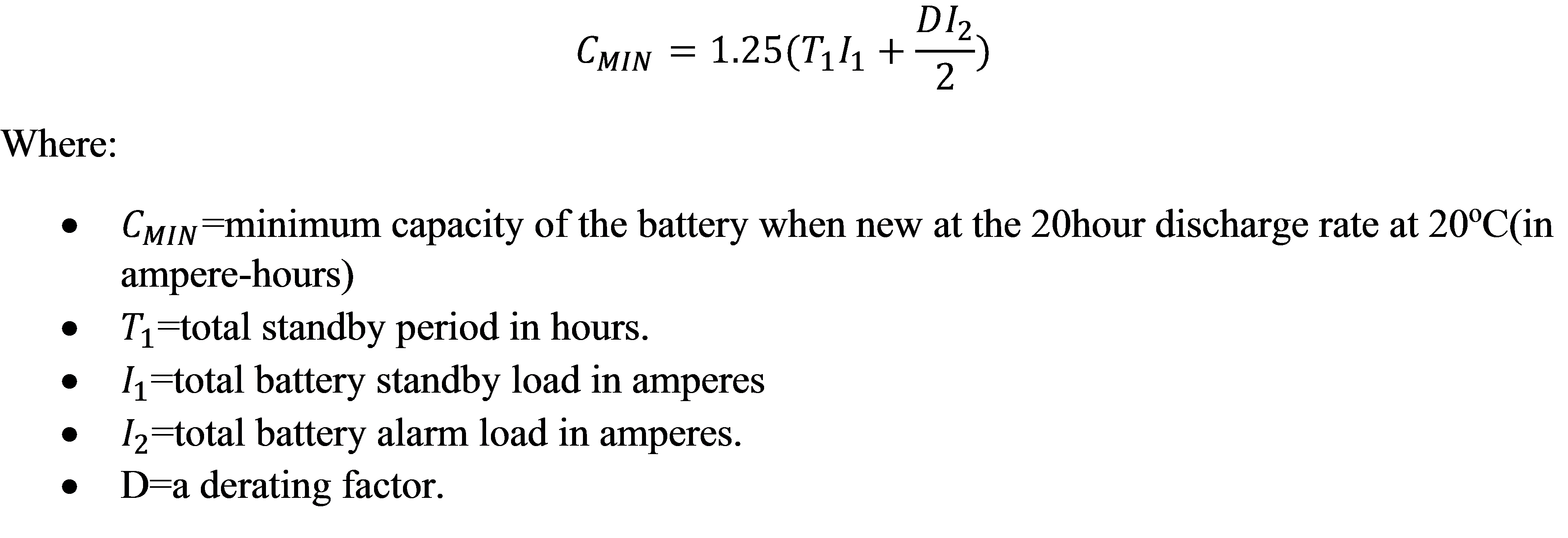
1.25 is a factor to allow for battery ageing.
The de-rating factor is intended to take into account the fact that the effective capacity of a battery depends on the rate at which it is discharged. Battery capacity is normally quoted at the
The de-rating is needed in cases in which the alarm current is sufficiently high to reduce the effective capacity below its nominal value.
Example 1: Category M or Category L systems.
Consider premises that are unoccupied from 6.00pm Friday until 9.00am Monday. Assume the normal operating current of the system is 350mA and the maximum alarm load is2.0A.The capacity of the standby batteries would be:

If, however, the circuit serving the fire alarm system is served by an automatically started generator, the capacity can be reduced to,
Example 2: Category P System
As the premises are unoccupied for 63 hours, a battery having

The next highest available capacity size should be used.
Cabling Considerations
Correct operation of a fire alarm system depends on the interconnections between the control equipment, detectors, call points and sounders. Unless these interconnections operate correctly when required, the system will not fulfil its intended functions. The components of most fire detection and alarm systems are connected by cables. For specialized applications where cabling cannot be used, fibre optics and/or radio links are used. Clause 27 of BS 5839-1 covers radio-linked systems.
These systems are ‘wireless’, in that all communications between control equipment and devices (manual call points, detectors and sounders) is carried out using radio transmission. Where fibre optic cables are used they should provide at least the same integrity and reliability as cables recommended for the same purpose.
When selecting cables for a fire alarm system due consideration should be given to the following:
- Resistance to fire
- Current carrying capacity.
- Voltage drop under maximum current conditions.
- Insulation characteristics.
- Mechanical robustness, resistance to corrosion and rodent attack, etc.
- Screening (where applicable).
- Suitability for carrying data (where applicable).
All cables used in fire detection and alarm systems (including those serving the mains supply to the system) must be
Cables used throughout the system (including that used for the final circuit providing mains voltage to the system) should comprise only one of the following types of cable:
- Mineral insulated copper sheathed cables. Conforming to BSEN 60702-1 and BSEN 60702-2
- Proprietary fire resisting cables that conform to BS 7629 (these are sometimes described as ‘
soft skinned ’ fire resisting cables). - Armoured fire resisting cables conforming to BS 7846.
- Cables rated at 300/500V (or greater) and that provide the same degree of safety to that afforded by cables complying with BS 7629.
Cables used for the installation of fire alarm systems, including those for the electrical supply, should whatever their design properties, have been independently tested and approved to BS EN 50200 PH30 for standard fire resistance or PH 120 BS8434-2 for enhanced fire resistance.
Conductor Sizes
When selecting conductor sizes, regard should be paid to physical strength and the limitations imposed by voltage drop. Voltage drop in a cable should not be such as to prevent devices from operating within their specification limits. Consideration should also be given to possible future extensions and some additional capacity left. For mechanical strength, cable conductors should have a
Segregation
There are four main reasons why fire alarm cables need to be segregated from the cables of other circuits.
- Breakdown of cable insulation of other circuits, from which fire alarm cables are not segregated, might affect the fire alarm system.
- A fault on another circuit could cause the cables of that circuit to catch fire, resulting in damage to the fire alarm cables.
- Electromagnetic interference from other circuits, from which there is inadequate separation distance and/or screening, could affect the operation of the fire alarm system.
- Strip out of
other cable could result in mechanical damage to the fire alarm cables.
It should also be ensured that there can be no interference between the mains voltage cables serving the fire alarm system and the lower voltage fire alarm circuits.
Choice of Detectors
Smoke Detectors will generally detect a fire far sooner than heat detectors. It is
Fixed Temperature Heat Detectors should be installed in areas where one would normally expect a sudden rise in temperature for instance kitchens and boiler rooms.
Rate of
Types of Smoke Detectors:
- Multisensor
High Performance Optical Smoke Detector- Optical Smoke Detector
Infra–Red Flame Detector- Optical Beam Detector
- Aspirating Detector
- Linear Heat Detector
- Duct Probe Unit
As each type of detector responds to a particular fire product, the relative speed of response of the detectors is therefore dependent upon the type of fire being detected.
As smoke is normally present at an early stage in most fires, smoke detectors (Ion Chamber, Optical,
Most fires, in their later stages, emit detectable levels of heat. Therefore in areas where rapid fire spread is unlikely and environmental conditions preclude the use of smoke detectors, heat detectors (Rate of
Fires tend to produce carbon monoxide, particularly in situations in which there is insufficient ventilation to enable fire to burn rapidly. Accordingly, carbon monoxide fire detectors provide useful warning of such fires. The carbon monoxide fire detector is well suited to provide early warning of slow
In situations where a burning liquid, for
Although heat, smoke and carbon monoxide detectors are suitable for use inside most buildings, flame detectors may be used to supplement these where necessary. Flame detectors need an unobstructed line of sight, their greatest use being for such special applications as the supervision of an outdoor storage area or an area where
Also available are specialized detectors which have been specifically designed for use in applications where point and line–type detectors cannot be used.
Two types are available, namely the Aspirating detector and Duct Probe Unit.
The Aspirating type detector comprises a small pump which draws a sample of air through holes in a pipe that is connected into a detector element. The detector element of the Aspirating detector is usually very much more sensitive than conventional point detectors to allow for the effects of dilution of smoke. This type of detector is normally used for protecting such areas as computer suites, clean rooms, or the interior of historic buildings where point or line–type detectors would look out of place.
Smoke Detector Spacing.
Spacing under Flat Ceilings.
In open spaces under flat horizontal ceilings, every point should lie within a horizontal distance of 7.5m from a smoke detector or 5.3 m from a heat detector.
This means that each point within the protected area must be covered by at least one detector; the coverage of a detector is a circle
The sensitive elements of smoke detectors should normally lie within the range of 25mm to 600mm from the ceiling, and for heat detectors within the range of 25mm to 150mm.
Stairways:
In enclosed stairways, fire detectors should be sited at the top of the stairway and on each main landing
An open stairway forms a path for
Corridors:
In
Obstructions.
Ceiling obstructions, such as structural beams, deeper than 10% of the overall ceiling height should be treated as walls. The area on each side of the obstruction should, therefore, be regarded as a separate area for the purpose of protection. The same applies in the case of partitions or storage racks that extend within 300mm of the ceiling.
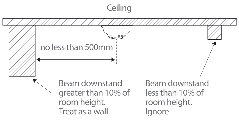
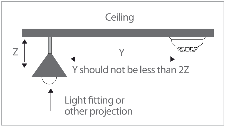
Where structural beams, ductwork, lighting fittings or other fixings to ceilings, not greater than 250mm in depth, create obstacles to the flow of smoke, detectors should not be mounted closer to the obstruction than twice the depth of the obstruction.
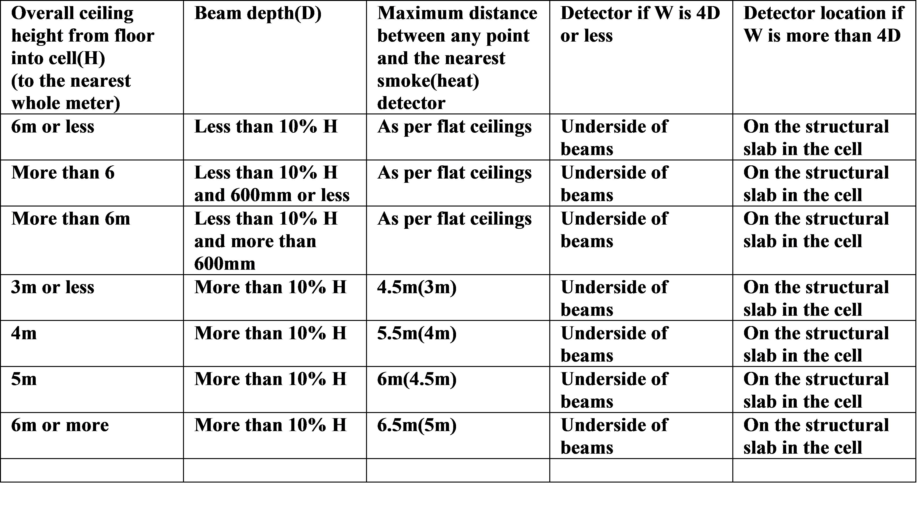
Honeycomb Ceilings.
Where a horizontal ceiling comprises a series of small cells, often referred to as a
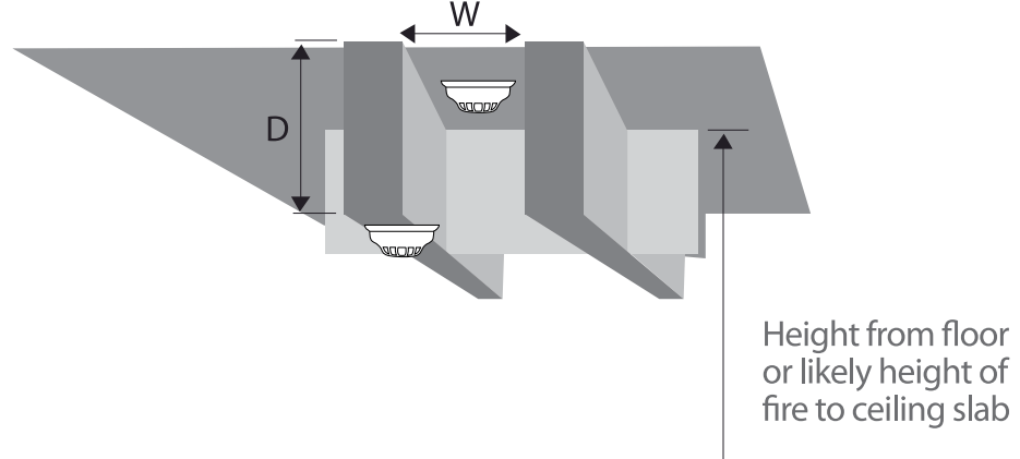
Horizontal ceiling comprising a series of small cells.
Key:
W: Width of
*Since mounting detectors at a depth of more than 600mm below the highest point in the protected spaces does not comply with 22.3d. , protection in these circumstances might need careful consideration to determine the most suitable location and spacing of detectors.
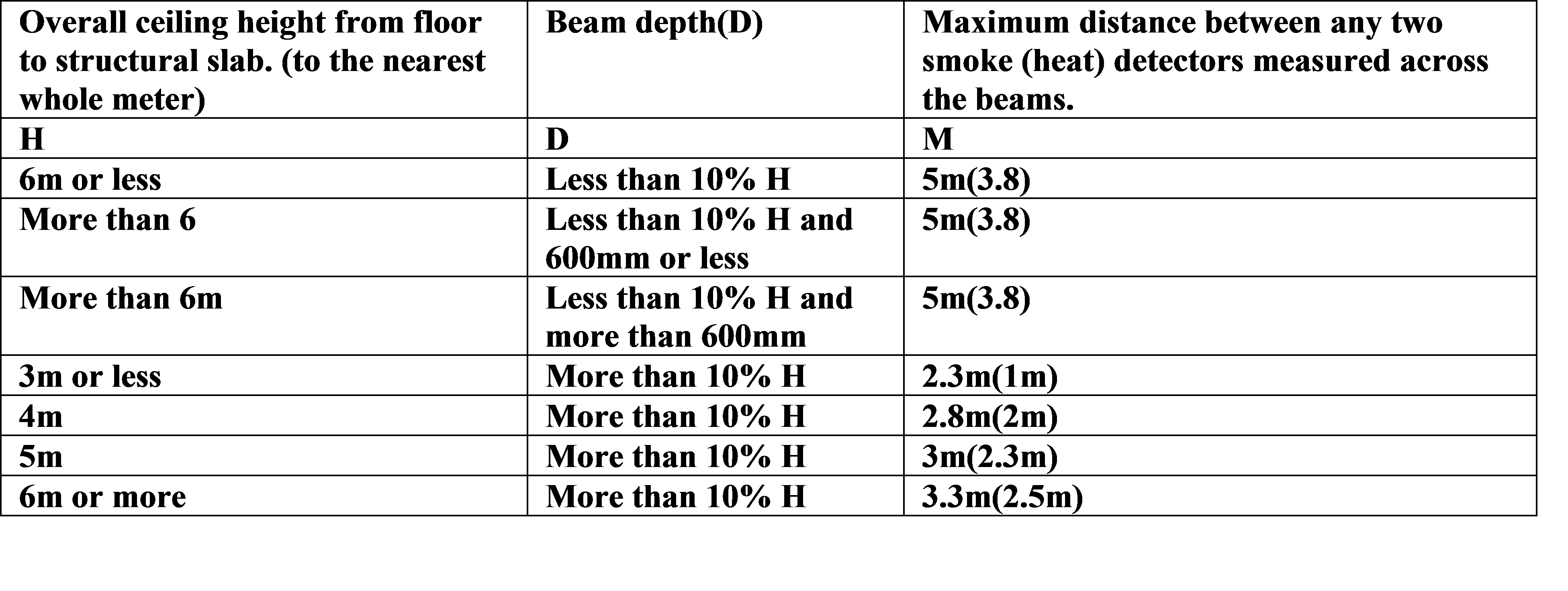
Closely Spaced Structural Beams and Floor Joists
Where there are a number of closely spaced structural beams, such as floor joists, a series of reservoirs for smoke, which BS 5839-1 refers to as ‘cells’, occur. Provided that the longer dimension of the cells is no more than L, then across the shorter cell dimension, the spacing, M, between detectors should be as given in Table 5 below. The spacing for the end detector to the end wall is half M. Detectors should be in the centre of the cells. If the longer dimension of the cells is more than L (see below), then the cell should be stopped to the depth of the beam and at no more than L. If this is impractical, detection should be installed in every cell.
L = 10.6m for smoke detectors.
L = 7.5m for heat detectors.
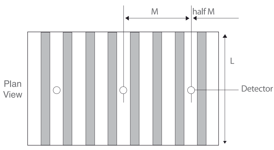
In this example, beam
Spacing and siting of detectors on ceilings with closely spaced structural beams or joists.
Ventilation
Ventilation systems in buildings should also be taken into account when designing fire systems because air movements in a space can have a number of effects on the operation of the devices.
Extraction systems can draw the fire products away from normally sited detectors, and fresh air inlets can stop clean air passing over detectors even when the room air is smoky. Increased air turbulence can give increased dilution of the smoke, and, in the case of ionization smoke detectors, clean air can cause a false alarm if it is moving fast enough.
Detectors should not be mounted directly in the fresh air input from air conditioning systems. In general, a spacing of not less than 1m between the detector and the air inlet should be maintained. Where the air inlet is through a perforated ceiling, the ceiling should be non-perforated for a radius of at least 600mm around each detector.
Control Equipment
The Fire Alarm Control Equipment should normally be sited in an area as follows:
- Preferably in an area of low fire risk and on the ground floor by the entrance used by the Fire Brigade and preferably viewable from outside of the building.
- It should be located in an area common to all building users and where automatic detection is in use, the Control Panel should be in a protected area.
- An alarm sounder should be sited next to the Control Unit, but not too near the telephone position.
Trackbacks/Pingbacks