This guide is intended for street lighting that is grid powered.
Why street lighting.
- For safety or security reasons.
Clear view of objects for comfortable movement.
It should be noted that the above are the main objectives and thus the lighting scheme should not be expected to give a
Design considerations:
Spacing of the street lights.Wattage of the street lights.- Light levels required.
- Type of lighting colour: Warm or Daylight?
- Warm light (yellow) penetrates darkness more than
day light and hence it is a common choice when it comes solar street lighting.
Lamps used in street lighting:
High pressure sodium lamp.- Metal Halide Lamps.
Low pressure sodium lamps.- Incandescent Lamp (not recommended).
- LED.
- CFL.
What you will find in this guide:
- Street illumination level calculations.
- Spacing between two light poles calculations.
- Street Light Luminaire calculations.
- Cable Sizing
- How to estimate the required power for the street light area:
- Energy Cost Calculations
- Pole Arrangement Schemes in Street (Road) Lighting Design
- Street Lighting Bills of Quantities
NOTE: This guide has been made as simple and practical as possible. It mostly applies to street lighting though some of its principles also apply to road lighting. Some concepts are mentioned in passing and the reader can research and read more on the same. There are details that have been deliberately omitted such as “Light intensity distribution of the lighting luminaire”, “Spread and Throw Angles of the luminaire” etc. In the near future, I may write a more detailed guide and also another one for “Market Lighting” and share the respective BOQs as well.
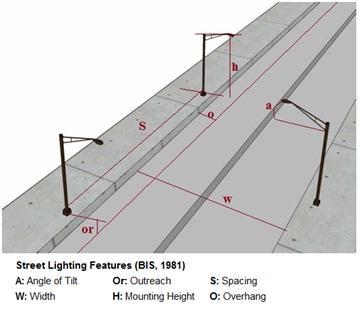
A.Street illumination level in Lux:

Where;
- AI=Average lumens.
- E = The illumination in Lux
- w = Width of the roadway
- d = Distance between luminaries
- UF = Utilization. Which is dependent on the type of fixture, mounting height, width of
roadway and the length of mast arm of outreach. - MF=Maintenance factor (normally 0.7 to 0.9).
The typical value of Al is
- 20500 lumens for 400 watts
- 11500 lumens for 250 watts
- 5400 lumens for 125 watts
- The value of Al varies depending upon the type of lamp specified.
B.Spacing between two light poles
Suppose you have two poles of street light having lamps rated at 300W, what is the ideal space between them if;
- Lamp output of the Lamp (LL) is= 33200 lumens.
- Required Lux Level (E) is =5 lux.
- Width of the road (W) = (11.48feet) 3.5 M
- Height of the pole (H) = (26.24feet) 8 M
- Utilization factor=0.19
- Lamp Lumen Depreciation Factor (LLD) = 0.8
- Luminaries dirt Depreciation Factor (LDD) = 0.9

The ideal spacing would be 24M. Note that the formula is based on “feet” as the unit of length.
C.Street Light Luminaire.
Suppose you have all other details required and you wanted to figure out the proper wattage of your lamps. For example, what would be the street light wattage of each luminaire of
- Road Details: The width of
road is 7 Meter. Distance between each Pole (D) is 50 Meter. - Required Illumination Level for Street Light (E) is 6.46 Lux per Square Meter.
- Luminous efficacy is 28 Lumen/Watt.
- Maintenance Factor (mf) 0.29, Utilization Factor (U.F) is 0.9.
Average Lumens (AI),
D.Cable Sizing:
It is important to size your cables properly so as to ensure that voltage drops do not exceed the recommended values.
To properly size your cables, you must consider these factors: the total load, load current, the cable length and the respect constant for the given load current.
The voltage drop on load conditions at a final sub-circuit;

Where:
(i) The current carrying capacity of the cable, = IR Amps
(ii) The load current; =IL Amps
(iii) The rated Voltage drop per Ampere per meter = Vd/A/m Volts
(iv) The length of
According to the IEE wiring regulation (BS 7671: 2008), 525-01-02 (17th Edition);
The maximum permissible voltage drop to a final sub-circuit= 4% of the nominal supply voltage.
For single phase (240V) the maximum permissible voltage drop; Vd =4%X240 = 9.6Volts
For Three phase (415V) the maximum permissible voltage drop; Vd =4% X415 =16.6Volts
For example, suppose that you have 6, 150W rated lamps.
Say, the total cable length that will be used is 100m (that’s, the last lamp will be located 100m from the transformer.
Total load= 150WX6=900W

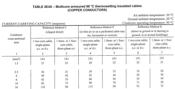
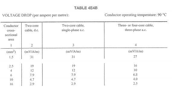
According to BS7671-2008, load current of 3.75A can be well accommodated by a 1.5mm2 copper cable. We are using BS7671-2008, Table 4E4A for cable sizing, and Table 4E4B for voltage drop
If we used the 1.5mm2 copper cable, the voltage drop would be:
Voltage drop=0.031×3.75×100=11.625V
11.625V exceeds the maximum voltage drop of 9.6V
We move to the next cable size, i.e, 2.5mm2,
If we used the 2.5mm2 copper cable, the voltage drop would be:
Voltage drop=0.019×3.75×100=7.125V
7.125V is very close to the limit of 9.6V, and since we must account for losses by the lamps themselves, temperature related constants, a 4mm2 cable would be appropriate as it would take care of such.
Thus, for this example, we will use a 4mm2 copper cable whose current rating is 49A for a single phase ac load. Based on our hypothetical load current of 3.75A.
Voltage drop=0.012×3.75×100=4.5V
Sure, the 4.5V drop is well within the limit of 9.6V. Thus,
Next is the MCCB sizing.
According to IEE regulations:
Il ≤ Ib ≤ Ic
Where:
- Il = Design current of the circuit.
- Ib = Nominal current or
current setting of the protective device. - Ic = Current carrying capacity of the conductor in the particular installation conditions.
In this case:
Il = 3.75A
Ic = 49A
Thus, you can choose any MCCB between 5A-30A. So we can choose 30A
E.How to estimate the required power for the street light area:
Suppose you have the following data, what will be the street light watt?
- Required Illumination Level for Street Light (L) is 6 Lux per Square Meter.
- Luminous efficacy (En) is 20 Lumen per Watt.
- Required Street Light Area to be illuminated (A) is 1 Square Meter.

F.Energy Cost Calculations:
Simply, the cost of running
The running cost of
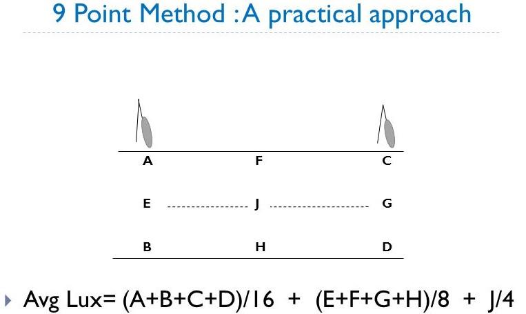
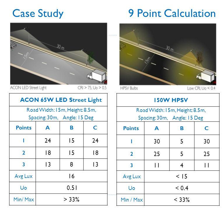
G.Overall Average Lux Level for Street Lighting:
The Average Lux Level of Street Light is measured by 9 point method.
Steps.
Make two equal quadrants between two street light poles on the lane of light poles (one side pole to
We have 3 points P1, P2 and P3 under the light pole then P4 & P7 are points opposite pole 1 or Point P3 same is applicable for P6 and P9 for Pole 2.
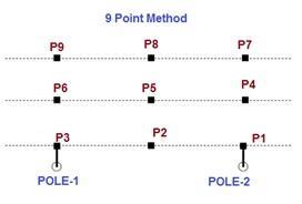

Note that there is another more accurate method, 12
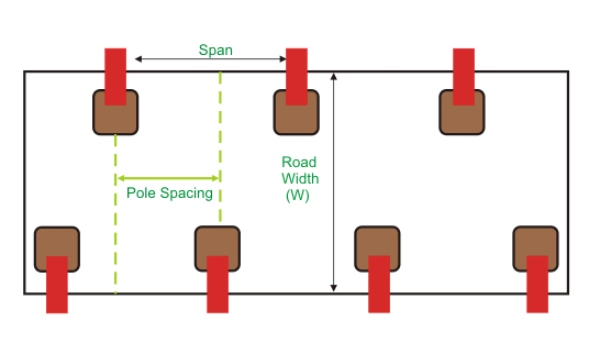
H.Pole Arrangement Schemes in Street (Road) Lighting Design:
Single Sided
When the width (W) of the street (road) is nearly equal to the pole height (H), i.e. W = H then the poles are arranged in one side only.
The span between
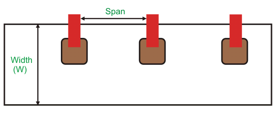
Double Sided
When the width (W) of the street (road) is nearly double the pole height (H), i.e. W = 2H then the poles are arranged along both sides in opposite to each other manner.
The span between two poles may not be equal to the road width.
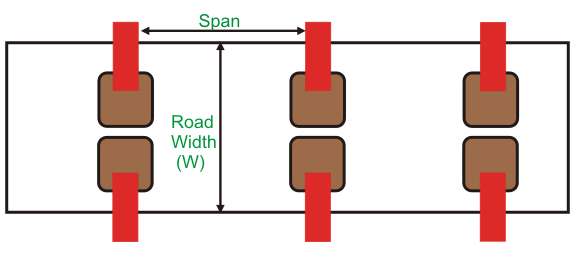
Staggered Sided or Zigzag Pattern
When the width (W) of the street (road) is nearly 1.5 times of the pole height (H), i.e. W = 1.5 H then the poles are arranged in both sides in
The span between two poles may not be equal to the road width.
I.Calculate Uniformity Ratio:
Once luminaries spacing has been decided, it is necessary to check the uniformity of light distribution and compare this value to the selected lighting
Uniformity Ratio ( UR) = Eav /Emin
E av = average maintained horizontal luminance.- Emin = maintained horizontal luminance at the point of minimum illumination on the pavement.
J.Street Lighting Bills of Quantities
- The bills of quantities for street lighting normally capture the following:
- Lighting points.
- The lighting fittings.
- Poles used and their type.
- Consumer units that may be used.
- Earthing facilities.
- Automatic Photocell cells units to automatically switch the lights on and off.
- Type and size of the holes for the poles.
The items mentioned above must be well described and their quantities well capture.
As a guide, you can download these two blank street lighting bills of quantities below in EXCEL and PDF
Excel Format:
Street Lighting BoQ-Blank BoQ 1
Street Lighting- BoQs -Blank BoQ 2
PDF formats:
Street Lighting- BoQs -Blank BoQ 2
Street Lighting BoQ-Blank BoQ 1
your company is very good 100%…i will be happy working with it as an electrician
What are the specifications for street lighting in residential zones, estates
Hello Barbara, the specifications depend on the size of the streets and also the way the houses are planned and spaced.
You can reach out to us for more detailed advice. We have emailed you.
Thank you.
Hallo don’t know if you can assist can you provide drawings and technical data of highmast, concrete poles and led lights
I’ve noticed that he’s a beautiful mind
The article is wonderful. We are a professional Chinese manufacturer specializing in the production of street lights. This article is prepared for our employee training purposes. If any of our African friends are interested in street lights, please feel free to contact us. We can have many cooperation approaches.