≈ 9 min read · June 5, 2023
As per Deutsch Norm DIN 5035
-
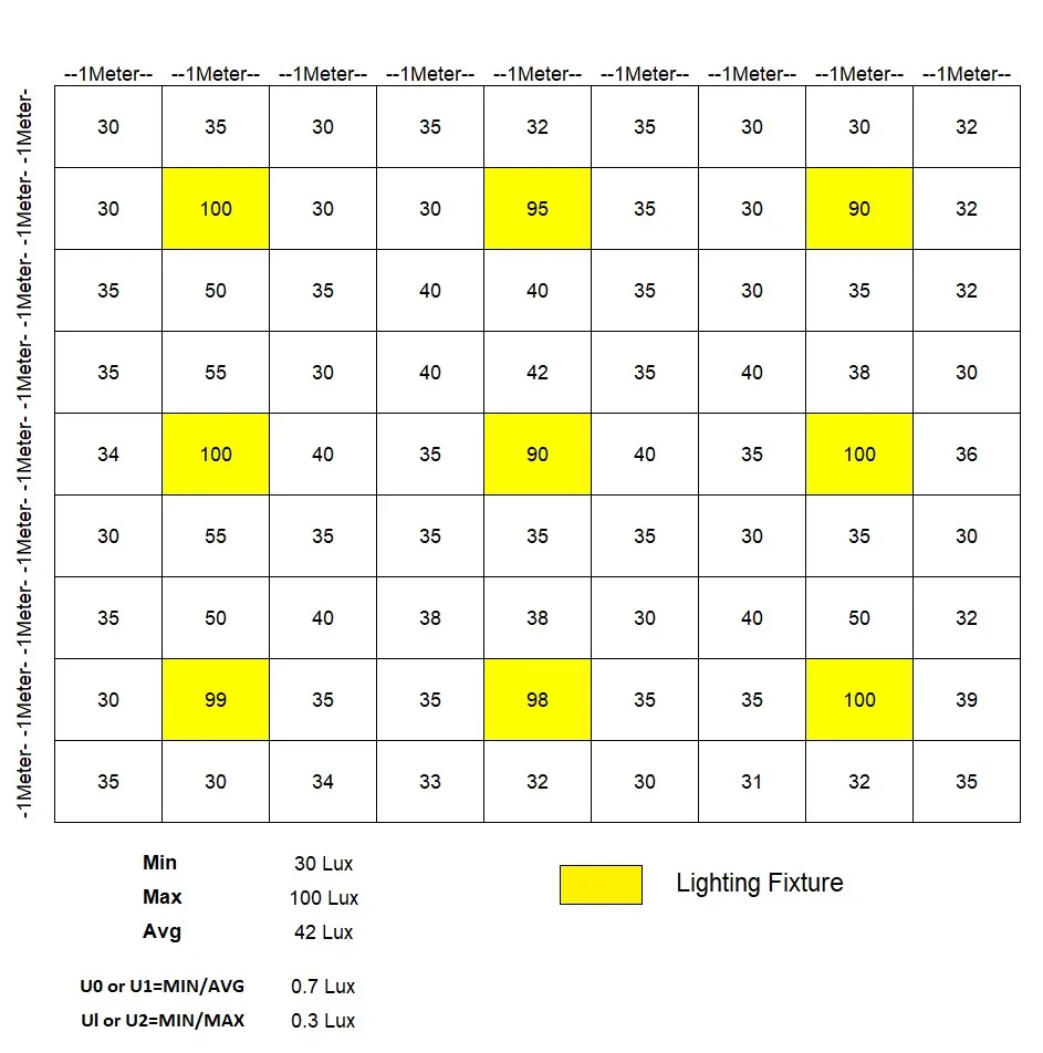
The DIN (Deutsche Industrie Normen) method for measuring illuminance offers flexibility and can adapt to various interior conditions. The methodology described breaks down the working plane into a grid, with each grid cell ideally being a square of at least 1 meter in size.
Here’s a bit more clarification on the steps:
- Establish a grid: Within each section, establish a grid with a minimum size of 1 meter. There should be a measurement point at the centre of each square.
- Define the grid module: The module defining the measurement points should be selected to not coincide with the luminaire grid in either principal direction. This is to avoid bias in the measurements and ensure they accurately reflect the overall illumination level of the room.
- Grid size adjustment: In large interiors, the grid size may be increased up to 5 meters. This flexibility allows the method to be applied effectively even in expansive areas.
- Measure obstructed interiors: If the working plane has large obstructions, areas between them are treated as separate spaces for the purpose of measurement. This unique aspect of the DIN method allows it to handle complex interiors and maintain accuracy in the results.
Remember, although the DIN method does not explicitly state accuracy limits, it’s crucial to ensure measurements are as precise and consistent as possible. Ensuring that your measuring instrument is correctly calibrated and that you are taking measurements under representative conditions can help improve the accuracy of your results.
Divide the working plane: The first step is to divide the working plane into sections. These sections should be rectangular and have a ratio of length to width of no less than 1:2. However, it’s preferable if they are square in shape.
OUTDOOR ILLUMINATION (LUX LEVEL) MEASUREMENT
Nine-Point Method for Determining Lux Levels in Street Lighting
- The Lux Level of Street Light is measured by the 9-point method.
- We need to make two equal quadrants between two light poles and between Pole and Rode edge.
- Two Measuring Points below the Light Pole (A1, A2) and Two opposite sides of the Pole at the Road Edge (A3, A4).
- Two Points between Pole and Road edge (B1, B3).
- One Point Between Pole (B2) and One Point between the opposite side of the Pole at the road edge (B4)
- One Point is at the centre (C1).
- Average Lux = (A1+A2+A3+A4)/16 + (B1+B2+B3+B4)/8 +C1/4

- Solution
| 26 Lux | 27 Lux | 13 Lux |
| 12 Lux | 15 Lux | 14 Lux |
| 26 Lux | 32 Lux | 22 Lux |
- Average Lux = (A1+A2+A3+A4)/16 + (B1+B2+B3+B4)/8 +C1/4
- Average Lux = (26+26+13+22)/16 + (12+27+14+32)/8 +15/4
- Average Lux =20Lux
| MIN | 12 Lux |
| MAX | 32 Lux |
| AVG | 20 Lux |
| U1=MIN/AVG | 0.58 |
| U2=MIN/MAX | 0.38 |
As per Grid Point Set Up Measurement
- Identify a horizontal grid of measurement points on the Illumination Measurement site surface. Locate measurement points on gridlines covering the test measurement area.
- Ensure that the spacing between measurement points is uniform in both directions and is less than one-half the pole height or less than 4.5 Meters, whichever is smaller.
- For installations with lights spaced less than 4.5 Meters apart, locate measurement points no farther apart than one-half the pole height, with at least three points between poles in both directions.
- Record the location of all measurement grids and point layouts with dimensions from surrounding poles or other structures. Provide this information, including a sketch or rendering of the grid layouts.
- For open areas such as the main parking, make the measurement grid large enough to cover at least four poles of this Area layout, and at least two poles are covered.
- For site perimeter open areas or areas adjacent to a building edge, establish the test area measurement grid in a typical perimeter or building edge area. The depth of the test area should extend from the paved site boundary or building edge inward to the nearest line of light poles that are at least 4.5 Meters from the boundary or building edge.
- The width of the test area must cover at least two of the poles in the line that is at least 4.5 Meters from the boundary or building edge.
(A) In Open Area

(B) In the Area of the Site Perimeter

(C) Near Site Boundary Area:

Grid Method to measure illumination on the road
- The arrangement of the measuring points depends on the distance between the Illumination Pole and the width of the Road.
- The measurement of illuminance should be performed on the area in a longitudinal direction with two consecutive luminaires in the same row and in a transverse direction the width of the area with the same illumination class, i.e. if the road and adjacent pavement or bicycle path have the same illumination class, they may be considered as one area during the measurements. The measuring points should be distributed evenly within the measuring field.
- The distance between the measuring points (D in Meter) in the longitudinal direction should be calculated using the formula
- The distance between the measuring point in longitude ( D)=S / N
- where:
S= the distance between the luminaires in [m],
N= the number of measurement points in the longitudinal direction,
for S ≤ 30 m, it is N = 10,
for S > 30 m, the smallest integer giving D ≤ 3 m. - The distance between measurement points (d in Meter) in the transverse direction should be calculated with the formula:
- The distance between the measuring point in transverse (d) = Wr / n
- where: Wr= the width of the road or the area under consideration in Meter.
- n = the number of measurement points in the transverse direction equal to 3 or more and is an integer giving d ≤ 1.5 m.
- The distance between the points and the edges of the surface under consideration should be D/2 in the longitudinal direction and d/2 in the transverse direction. The location of the measurement points in the measuring field is shown in Figure.

Equal Space Method
- In this method, at least 10 equal measuring Points are taken between two lighting poles on one side of the Roadway.
- These measurement points cannot be spaced more than 5 meters apart. Two lines of measurement points are needed per driving lane, one-half lane width apart.
- Once you have taken all of your illuminance measurements, you can calculate an average illuminance for the section of the roadway you have measured.

What is Lighting Uniformity
- light uniformity refers to the uniformity of lighting in an environment. It is necessary to maintain light uniformity to ensure everything is perfectly visible in the room.
- Uniformity is the minimum lighting level ratio to the average lighting level in a specified area.
- U1 = E Min / E Average
- U2 = E Min / E Maximum
- U & E stand for uniformity & illuminance, respectively.
- Uniformity is a quality parameter for the overall illuminance distribution.
- Using this uniformity ratio to describe how the lights are evenly distributed on the ground is quite useful. If the difference between the minimum and average lux is small, the ratio is high, giving better light uniformity.
- The maximum lighting uniformity is 1, which means the lux levels in all the sampling points are the same. However, it is very unlikely to achieve this maximum value for artificial lighting.
- If the uniformity is very low for the outdoor or indoor lighting, the citizens, workers, or athletes might feel uncomfortable, and thus their vision is affected.
- The more uniform the light distribution, the better the illuminance and the more comfortable the visual experience. The closer the illuminance uniformity is to 1, the better; otherwise, the smaller the more visual fatigue.
How to Improve Lighting Uniformity
- Adjust the aiming angle of the floodlight,
- The lights irradiated by the floodlights should overlap each other,
- Use pole lights, high-power floodlights, street lights, etc. to supplement lighting.
Light Uniformity Standard
- Different light uniformity standards need to be followed depending on the nature of the environment.
- Most focus-intensive tasks require a uniformity index of around 0.6, whereas technical drawing and other demanding tasks require a ratio of at least 0.7.
- A uniformity value greater than 0,60 is recommended in working areas. Because, above this level, the change in light levels cannot be sensed by people, making them comfortable. Proper lighting of the environment also helps employees work more comfortably when looking at the computer screen.
- Due to low uniformity in road lighting, the homogeneity of lighting will be distorted. So, very bright and very dark spots will occur on the road. If brightness changes very often, this will cause eye strain and stresses the drivers.
- In order to avoid these situations, an average uniformity value greater than 0.35 or 0.4 is required according to road lighting class.
| Standard | Area | The ratio of Minimum/Average Illumination |
| UK CIBSE and German DIN guidelines | The general lighting scheme | 0.6 and 0.8 |
| NBC-2005, page no 759 | Working Area | Not Less than 0.7 |
|
Table-6: Recommended Levels of Illumination (BIS, 1981) |
||
| Type of Road | Road Characteristics | The ratio of Minimum/Average Illumination |
| A-1 | Important traffic routes carrying fast traffic |
0.4 |
| A-2 | Main roads carrying mixed traffic like city main roads/streets, arterial roads, throughways |
0.4 |
|
B-1 |
Secondary roads with considerable traffic, like local traffic routes, shopping streets |
0.3 |
| B-2 | Secondary roads with light traffic |
0.3 |
|
EUROPEAN STANDARD- EN 12464-1:2011 |
|
|
Space |
Uniformity U0 (Emin / Em) |
|
Areas with traffic and corridors |
0.4 |
| Stairways, escalators, and travelators |
0.4 |
|
Lifts |
0.4 |
| Loading bays |
0.4 |
|
Coffee-break rooms |
0.4 |
| Technical facilities |
0.4 |
|
Storage spaces |
0.4 |
| Electronics workshops, testing, and adjustments |
0.7 |
|
Ball-mill areas and pulp plants |
0.4 |
| Offices and writing |
0.6 |
|
Check-out areas |
0.6 |
| Waiting rooms |
0.4 |
| Kitchens |
0.6 |
|
Parking areas |
0.4 |
| Classrooms |
0.6 |
| Auditoriums |
0.6 |
|
EUROPEAN STANDARD- EN 12464-1:2011 |
|
| Task illuminance | ≥ 0.7 |
| The illuminance of immediate surrounding areas | ≥ 0.5 |
|
|
Football Field Lighting Design |
||
| Nature of the Sports Field | Required U1 Light Uniformity | ||
| Class I, such as for a National Competition | ≥ 0.7 | ||
| Class II, such as for a League | ≥ 0.6 | ||
| Class III, such as for a Training Ball Field | ≥ 0.5 | ||
|
|
Industrial and Commercial Lighting Uniformity Requirement |
||
| The Area | The Light Uniformity Standard | ||
| Highway | 0.4-0.6 | ||
| Sports field | 0.5-0.8 | ||
| Office | 0.4-0.6 | ||
| Parking Lot | 0.4-0.5 | ||
| Warehouse | 0.4-0.6 | ||
| Running Track | 0.3-0.5 | ||
| Airport | 0.2-0.3 | ||
Greetings,
The nine point method seems to be very convenient to take actual Illumination values on-site. Much simpler than the actual grids in different standards. Do you have documentation about the method, as I can’t seem to find anything on the web about it specifically for roadway lighting? I’dd also like to know where the /16, /8 and /4 values come from in the average Illumination calculation.
Best regards